Project Arduino – Ohm’s law
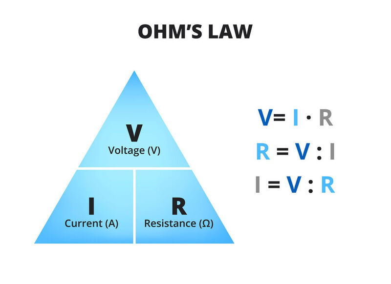
Ohm’s law is a fundamental principle in electrical engineering that relates the voltage, current, and resistance of a circuit. It states that the current through a conductor is directly proportional to the voltage across it and inversely proportional to its resistance.
The formula is V = IR, where V is the voltage, I is the current, and R is the resistance.
It’s an essential concept for anyone working with electrical circuits.
A simple usecase to use the formula is for example to light up a LED in a circuit. When you add an LED to a circuit without a resistor, the voltage across the LED will be determined by the other components in the circuit. In this case 5V is too high, and the LED will draw too much current and become overheated, which can cause it to burn out or fail.

In contrast, adding a resistor to the circuit helps to limit the amount of current flowing through the LED, protecting it from damage. The resistor reduces the voltage across the LED to a safe level, preventing it from overheating and burning out.
Therefore, it is crucial to add a resistor in series with an LED to limit the current and prevent it from burning out.
You can calculate how much resistance you need with Ohm’s law. The voltage in this case is 5. The LED itself uses voltage that you can subtract. For a typical red LED that’s about 1.5V. The LED will light up with a current of about 0.02 A. With Ohm’s law, we can now calculate the amount of resistance.
Resistance = 3.5 V / 0.02 A
Which is about 180 ohm!

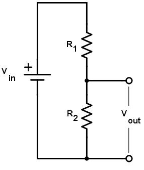
Great usage of the formula is when calculating a voltage divider for example a potentiometer. A voltage divider is a circuit that can divide a voltage into a lower value. It consists of two resistors in series, connected across a voltage source. The voltage across each resistor can be calculated using Ohm’s law.