
Project Arduino – Duty Cycle
TL;DR
based on the following pseudo code
TURN LED ON
delay(2)
TURN LED OFF
delay(6)
So what is the Frequency?
frequency = 1000ms / (2ms+6ms) hertz
So what is the Duty Cycle?
Duty Cycle = 2 / (2+6) (%)
In this example
Frequency = 125 hertz (125 changes per sec)
Duty Cycle = 25% (so it works on 25% of the power)
In the world of electronics and circuit design, there are various techniques used to control power and voltage levels delivered to different components. One such technique that plays a crucial role in numerous applications is Pulse Width Modulation (PWM). In this article, we will delve into the concept of PWM and explore the significance of its key parameter, the duty cycle.
What is PWM? Pulse Width Modulation, or PWM, is a method of controlling the average power or voltage level supplied to a load. It achieves this by rapidly switching a digital signal between two states: ON and OFF. By varying the duration of these states, PWM can effectively adjust the average power or voltage delivered to the load.
The duty cycle is a fundamental aspect of PWM. It represents the ratio of the pulse width (ON time) to the total period of the signal. Typically expressed as a percentage, the duty cycle plays a vital role in determining the average power or voltage level applied to the load.
For instance, if we have a PWM signal with a pulse width of 2 milliseconds and a total period of 10 milliseconds, the duty cycle would be calculated as follows: (2 / 10) * 100 = 20%. This means that the signal is ON for 20% of the time and OFF for the remaining 80% of the time.

The duty cycle directly influences the average power or voltage level delivered to the load. A higher duty cycle translates to a longer pulse width, meaning the signal remains ON for a larger portion of the total period. Consequently, this results in a higher average power or voltage level being applied to the load.
Conversely, a lower duty cycle corresponds to a shorter pulse width, with the signal spending less time in the ON state. As a result, the average power or voltage level decreases. By adjusting the duty cycle, precise control over the output can be achieved in various applications.
The Arduino can only output two voltages – 0 volts and 5 volts. But many devices like LEDs, servos, and motors need to be powered by a range of voltages between 0 volts and 5 volts. Luckily, the Arduino is capable of pulse width modulation, which can be used to simulate any voltage between 0 volts and 5 volts. Use the following pins and use the following code to write to them
analogWrite(pin, value);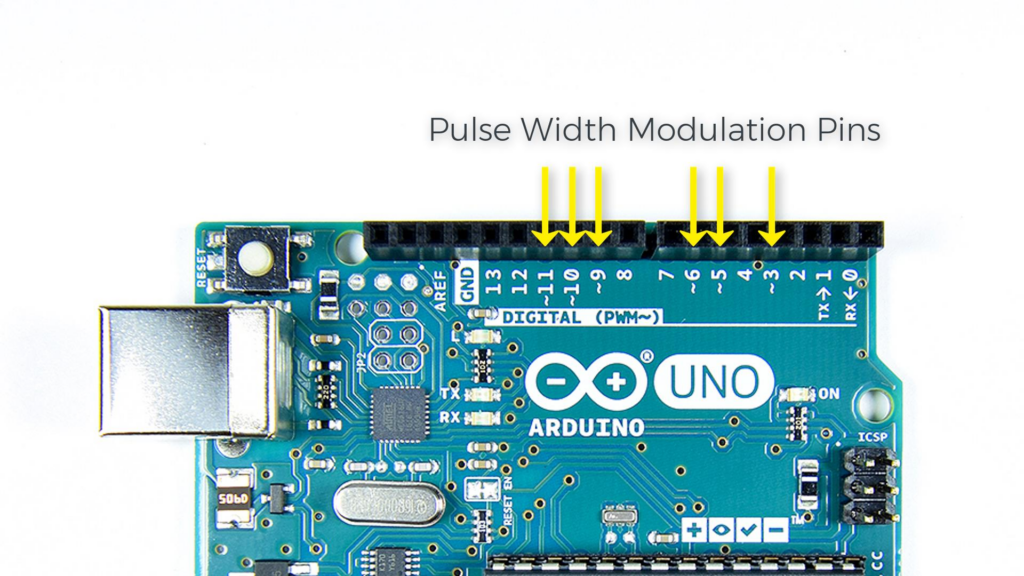
In this example, I used a potentiometer to dim the lights accordingly
with the following code
// Definieer A0 als analoge ingang voor de potmeter:
   const int analogInPin = A0;
// Definieer D9 als output voor het PWM-signaal:
   const int analogOutPin9 = 9;
// Definieer D11 als output voor het PWM-signaal:
   const int analogOutPin11 = 11;
// Stel variabele van potmeter in op 0:
   int sensorValue = 0;
// Stel variabele voor PWM-signaal in op 0:
   int outputValue9 = 0;
// Stel variabele voor PWM-signaal in op 0:
   int outputValue11 = 0;

void setup() {
}

void loop() {
   sensorValue = analogRead(analogInPin);

   outputValue9 = map(sensorValue, 0, 1023, 0, 255);
   outputValue11 = map(outputValue9, 0, 255, 255, 0);

   analogWrite(analogOutPin9, outputValue9);
   analogWrite(analogOutPin11, outputValue11);

   delay(2);
}