
Project Arduino – Components
Semi-Conductors
A semiconductor is a material that can act like both a conductor and an insulator. This makes it useful for making electronic devices like transistors and computer chips. By adding tiny amounts of other materials to the semiconductor, we can control how it conducts electricity and use it to create electronic components.
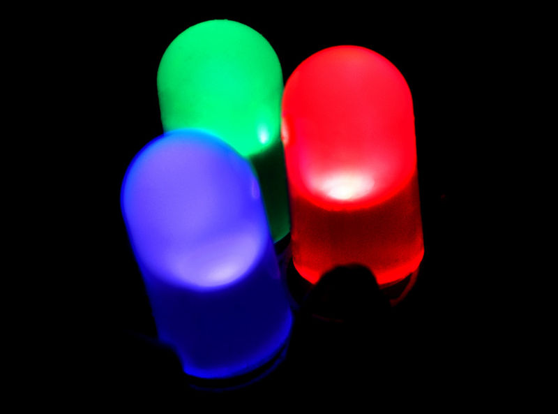
A Light Emitting Diodes (LEDs) are a type of semiconductor device that emits light when a current is passed through them. But more importantly, a LED is also a diode. A diode is a semiconductor device that allows current to flow in one direction while blocking it in the opposite direction.
Resistor
A resistor is another common electronic component that is used to limit the flow of current in a circuit.
A resistor is a passive electronic component that is made of a material with high resistance to the flow of electricity. When a voltage is applied across a resistor, the flow of current through the resistor is limited by its resistance, which is measured in ohms (Ω).
To read a resistor table, you first need to know the color code for the resistor. Resistor color codes use a series of colored bands to represent the resistance value and tolerance of the resistor.
The most common color code for 4-band resistors uses the following color code sequence:
- The first band represents the first digit of the resistance value.
- The second band represents the second digit of the resistance value.
- The third band represents the multiplier (i.e., number of zeros) for the resistance value.
- The fourth band represents the tolerance of the resistor.
To read the value of a resistor using the color code, follow these steps:
- Determine the color of each band, starting from the band closest to one end of the resistor.
- Use a resistor color code chart to find the corresponding value for each color.
- Calculate the resistance value by combining the values from the first two bands, and multiplying the result by the value from the third band. For example, if the first two bands are brown and black, and the third band is red, the resistance value would be 10 x 1 = 10 ohms.
- Check the tolerance value from the fourth band to determine the range of acceptable values for the resistor.

Placement of Resistor
In a basic electronic circuit with an LED and a resistor, it doesn’t matter where the resistor is located in the circuit, as long as it is present and its value is appropriate for the circuit.
The purpose of the resistor in this circuit is to limit the amount of current that flows through the LED. LEDs have a characteristic voltage drop, which means that a specific voltage is required for the LED to turn on and start conducting current. If too much current flows through the LED, it can be damaged or destroyed.
By placing a resistor in series with the LED, the resistor limits the amount of current that flows through the LED, ensuring that it operates within its safe range. As long as the value of the resistor is appropriate for the circuit, it will limit the current flowing through the LED regardless of whether it is placed before or after the LED in the circuit.
However, the placement of the resistor can affect the overall performance of the circuit. If the resistor is placed before the LED, it will also limit the current flowing through any other components in the circuit. If the resistor is placed after the LED, it will not limit the current flowing through other components in the circuit. So the placement of the resistor can affect the behavior of the circuit as a whole, but it won’t affect the LED’s protection against excessive current flow.
Video
Here is a video of two LEDS blinking after each other. Both need a resistor to operate because both are controller by their own output from the Arduino.
Superb posts! Have a look at my page 87N where I also put in extra effort to create quality information about Cosmetics.